Edging - A Canny Edge Detection Implementation
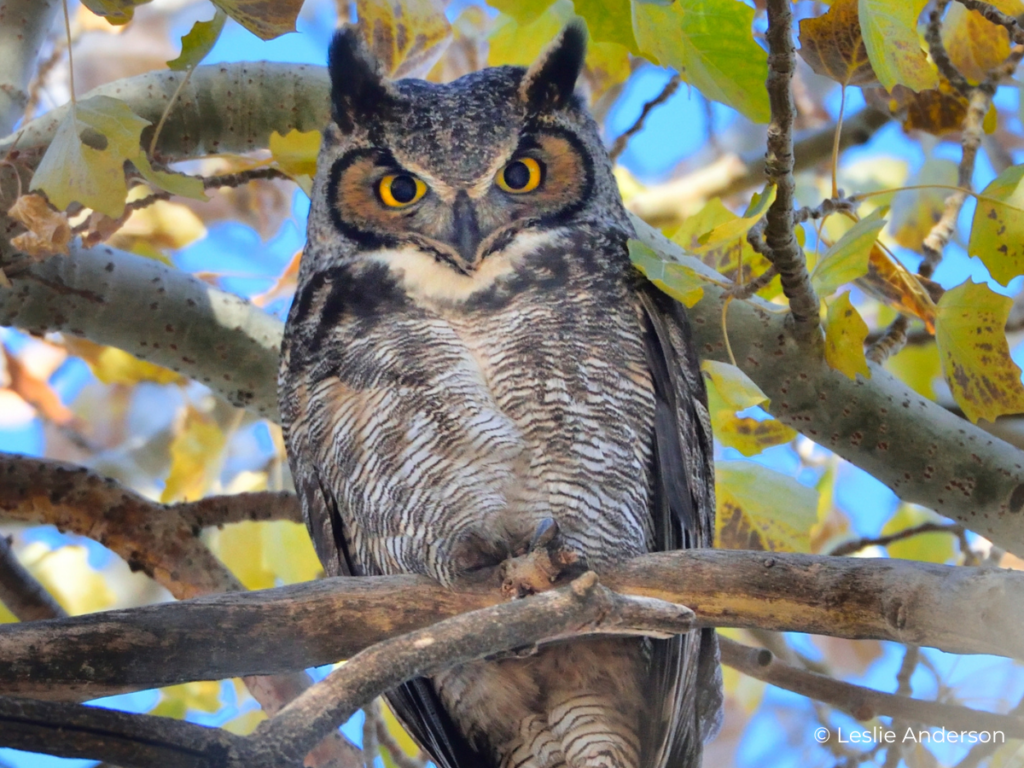
For the past two months or so, I’ve only done work-related programming. So to take the edge off, I decided to do some recreational programming and it popped into my head to try to implement edge detection. It’s something I’d never done before and knew nothing about, so I knew it was sure to be a fun learning experience.
Code: Github
Like I said, I knew nothing about edge detection. So my first step was finding out the best (and/or easiest to implement) algorithm used for edge detection. I stumbled on this article, which served as a good starting point and also helped me decide on which algorithm to implement: the canny edge detection algorithm.
I wanted to implement this in either C++ or Rust, to improve my skills and feel for either. I later decided to use Rust because the US government says I should.
Also, it is at this point where I complain that most articles/tutorials on this topic are not only in Python but end up using some library that obfuscates the actual important logic behind the steps in this algorithm (OpenCV, I’m looking at you).
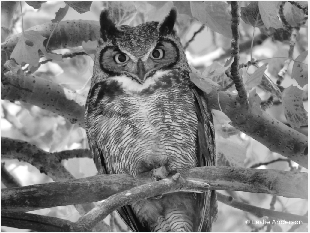
Step 1: Grayscale
The first step in the canny edge detection algorithm is applying a grayscale filter. Most non-grayscale images use either RGB or RGBA pixel representation. R G B standing for Red Green and Blue, with the A standing for Alpha (the transparency of the pixel). Each with values ranging from 0 to 255 (so 8 bits or an unsigned byte). This means that in an image using RGB every 3 byte values represent a single pixel, and with RGBA every 4 byte values represent a single pixel.
Knowing the number of bytes that make up a single pixel (what I like to call pixel width) is important for iterating over the image’s individual pixels. If you used an RGB image in a grayscale implementation built for RGBA images only, it would mess up the image completely.
The last thing to consider is the grayscale method. There are three accepted methods of grayscaling I could find:
- Average Method: you find the average of the RGB values of the pixel.
- Luminosity Method: sum of the multiplication of each RGB value by a ratio of how they are perceived.
- Weighted Average Method: an improved version of the luminosity method, with better perceived ratios.
But once you know the pixel width and the grayscale method you want to use, applying a grayscale filter becomes trivial.
enum Luminosity {
    Red,
    Green,
    Blue,
}

// called Luminosity, but uses the weighted average values
impl Luminosity {
    fn value(self) -> f32 {
        match self {
          Luminosity::Red => 0.299,
          Luminosity::Green => 0.587,
          Luminosity::Blue => 0.144,
        }
    }
}

fn grayscale(src: &[u8], px_width: usize) -> Vec<u8> {
    // the size of the resulting vector is the size of the input array
    // scaled down by the image pixel width.
    // this is because in Grayscale format, the pixel width is 1
    let mut dst = vec![0; src.len() / px_width];
    let mut i = 0;
    while i < src.len() - px_width + 1 {
        let lum = match px_width {
          // if this pixel width is 1,
          // then we can assume the image is already grayscale
          1 => src[i],
          3 | 4 => {
            (src[i] as f32 * Luminosity::Red.value()
             + src[i + 1] as f32 * Luminosity::Green.value()
             + src[i + 2] as f32 * Luminosity::Blue.value()) as u8
          }
          _ => unreachable!(),
        };

        // set the pixel value in the new image vector to the sum of the ratios.
        dst[i / px_width] = lum;
        // go to the start of the next pixel
        i += px_width;
    }

    dst
}
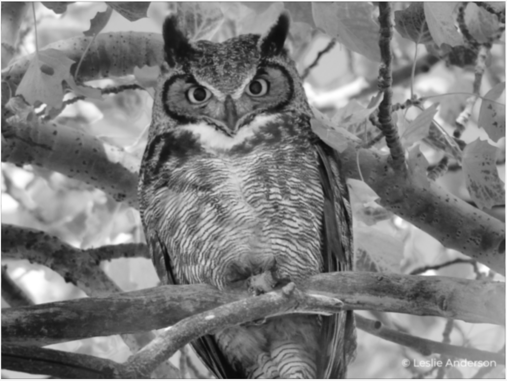
Step 2: Gaussian Blur
According to wikipedia, Gaussian blur is the result of blurring an image using a Gaussian function. Quite the definition right?
Essentially, in this step you’re smoothening the edges in the image and reducing the overall image noise. Who would have thought that to detect edges you’d need to make the image less… edgy.
The Gaussian function (in one dimension) is defined as this beauty:

In practice, it is best to take advantage of the Gaussian blur’s separable property by dividing the process into two passes. In the first pass, a one-dimensional kernel is used to blur the image in only the horizontal or vertical direction. In the second pass, the same one-dimensional kernel is used to blur in the remaining direction. The resulting effect is the same as convolving with a two-dimensional kernel in a single pass, but requires fewer calculations.
For this reason, I utilized the 1-D Gaussian function and simply applied the resultant kernel in both directions.
const KERNEL_RADIUS: i32 = 2;
const KERNEL_SIZE: usize = (KERNEL_RADIUS * 2 + 1) as usize;

fn gaussian_blur(mut src: Vec<u8>, image_width: i32) -> Vec<u8> {
    let mut dst = vec![0; src.len()];
    let mut kernel: [f64; KERNEL_SIZE] = [0.0; KERNEL_SIZE];
    let mut sum = 0.0;

    let sigma: f64 = ((KERNEL_RADIUS / 2) as f64).max(1.0);

    // compute kernel for 1D gaussian blur
    for x in -KERNEL_RADIUS..=KERNEL_RADIUS {
        let exponent = -(x * x) as f64 / (2.0 * sigma * sigma);
        let numerator = std::f64::consts::E.powf(exponent);
        let denominator = 2.0 * std::f64::consts::PI * sigma * sigma;

        let kernel_value = numerator / denominator;
        kernel[(x + KERNEL_RADIUS) as usize] = kernel_value;
        sum += kernel_value;
    }

    // normalize kernel
    (0..KERNEL_SIZE).for_each(|x| {
        kernel[x] /= sum;
    });

    // apply kernel in x direction
    (0..src.len()).for_each(|px| {
        let mut new_pixel = 0.0;

        for kernel_x in -KERNEL_RADIUS..=KERNEL_RADIUS {
            let kernel_value = kernel[(kernel_x + KERNEL_RADIUS) as usize];

            let neighbor_px = px as i32 + kernel_x;

            if neighbor_px < 0 || neighbor_px >= src.len() as i32 {
                continue;
            }

            let npx = src[neighbor_px as usize] as f64 * kernel_value;
            new_pixel += npx;
        }

        dst[px] = new_pixel as u8;
    });

    // apply kernel in y direction
    (0..dst.len()).for_each(|py| {
        let mut new_pixel = 0.0;

        for kernel_x in -KERNEL_RADIUS..=KERNEL_RADIUS {
            let kernel_value = kernel[(kernel_x + KERNEL_RADIUS) as usize];

            let neighbor_py = py as i32 + kernel_x * image_width;

            if neighbor_py < 0 || neighbor_py >= dst.len() as i32 {
                continue;
            }

            let npx = dst[neighbor_py as usize] as f64 * kernel_value;
            new_pixel += npx;
        }

        src[py] = new_pixel as u8;
    });

    src
}
In our implementation, we assume that the input image byte array has a pixel width of 1 (i.e. grayscale has been applied). This allows us to simplify the implementation by taking every index of the byte array as a sole pixel in the image. We first apply the kernel in the x dimension and store the results in dst. Then we apply the kernel in the y dimension and store the results back in src (as we don’t want the results from previous iterations in the y dimension to affect our results).
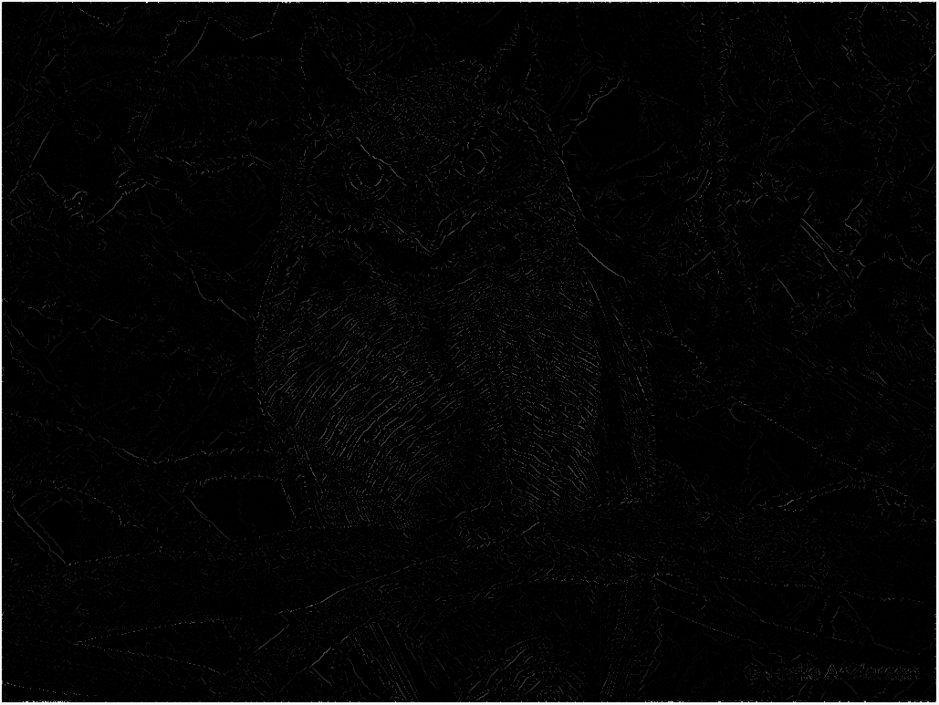
Step 3: Sobel Filter
The Sobel-Feldman operator is used in this step to find the intensity gradients of the image. This is done by convolving (applying) 3x3 kernels in the x and y direction.

Where A is the source image.
The results of the kernel convolutions are used to calculate:
-
the Gradient magnitude
-
and the Gradient direction


The gradient direction is further rounded to one of 0, 45, 90 or 135 degrees. These two values (G and Θ) are crucial for the next step.
fn sobel_filter(src: &[u8], image_width: i32) -> Vec<i32> {
    let mut dst = vec![0; src.len() * 2];

    let kernel_x = [[1, 0, -1], [2, 0, -2], [1, 0, -1]];
    let kernel_y = [[1, 2, 1], [0, 0, 0], [-1, -2, -1]];

    // apply kernel in x direction
    (0..src.len()).for_each(|px| {
        let mut new_pixel: i32 = 0;

        for x in -1..=1 {
            for y in -1..=1 {
                let kernel_value = kernel_x[(x + 1) as usize][(y + 1) as usize];

                let neighbor_px = px as i32 + x + (y * image_width);

                if neighbor_px < 0 || neighbor_px >= src.len() as i32 {
                    continue;
                }

                let npx = src[neighbor_px as usize] as i32 * kernel_value;
                new_pixel += npx;
            }
        }

        dst[px * 2] = new_pixel;
    });

    // apply kernel in y direction
    (0..src.len()).for_each(|py| {
        let mut new_pixel: i32 = 0;

        for x in -1..=1 {
            for y in -1..=1 {
                let kernel_value = kernel_y[(x + 1) as usize][(y + 1) as usize];

                let neighbor_px = py as i32 + x + (y * image_width);

                if neighbor_px < 0 || neighbor_px >= src.len() as i32 {
                    continue;
                }

                let npx = src[neighbor_px as usize] as i32 * kernel_value;
                new_pixel += npx;
            }
        }

        // calculate gradient magnitude and gradient direction
        let ndst = (dst[py * 2].pow(2) + new_pixel.pow(2)) as f32;
        let angle = (new_pixel as f32)
            .atan2(dst[py * 2] as f32)
            .to_degrees()
            .abs();
        dst[py * 2] = ndst.sqrt().ceil() as i32;
        // round angle
        let angle = match angle {
            0.0..=22.5 | 157.5..=180.0 => 0,
            22.5..=67.5 => 45,
            67.5..=112.5 => 90,
            112.5..=157.5 => 135,
            _ => panic!("Unexpected angle: {}", angle),
        };
        dst[py * 2 + 1] = angle;
    });

    dst
}
Step 4: Non-Max Suppression
This step (also called gradient magnitude thresholding or lower bound cut-off suppression) entails using the results from the sobel filter step to determine if a pixel is truly an edge.
We check each pixel’s gradient magnitude is the greatest of its neighboring pixels in its gradient direction. If it does, then we preserve its value. Else, we set its value to zero.
How do we know the neighboring pixels in its gradient direction? Wikipedia can help us with that:
if the rounded gradient angle is 0° (i.e. the edge is in the north-south direction) the point will be considered to be on the edge if its gradient magnitude is greater than the magnitudes at pixels in the east and west directions,
if the rounded gradient angle is 90° (i.e. the edge is in the east-west direction) the point will be considered to be on the edge if its gradient magnitude is greater than the magnitudes at pixels in the north and south directions,
if the rounded gradient angle is 135° (i.e. the edge is in the northeast-southwest direction) the point will be considered to be on the edge if its gradient magnitude is greater than the magnitudes at pixels in the north-west and south-east directions,
if the rounded gradient angle is 45° (i.e. the edge is in the northwest-southeast direction) the point will be considered to be on the edge if its gradient magnitude is greater than the magnitudes at pixels in the north-east and south-west directions.
With the above information, the implementation becomes simple:
fn gradient_thresholding(src: &[u8], image_width: usize) -> Vec<u8> {
    let src = sobel_filter(src, image_width as i32);
    let image_width = image_width * 2;
    let mut dst = vec![0; src.len() / 2];

    let sobel_max = *src.iter().max().unwrap();

    let mut px = 0;
    while px < src.len() {
        let mut new_pixel = 0;

        let angle = src[px + 1];
        let mut cmp_pxs: [i32; 2] = [0; 2];
        match angle {
            0 => {
                cmp_pxs[0] = px as i32 - 2;
                cmp_pxs[1] = px as i32 + 2;
            }
            45 => {
                cmp_pxs[0] = px as i32 - image_width as i32 + 2;
                cmp_pxs[1] = px as i32 + image_width as i32 - 2;
            }
            90 => {
                cmp_pxs[0] = px as i32 - image_width as i32;
                cmp_pxs[1] = px as i32 + image_width as i32;
            }
            135 => {
                cmp_pxs[0] = px as i32 - image_width as i32 - 2;
                cmp_pxs[1] = px as i32 + image_width as i32 + 2;
            }
            _ => panic!("Unexpected angle: {}", angle),
        };

        for cmp_px in cmp_pxs {
            if cmp_px < 0 || cmp_px >= src.len() as i32 {
                continue;
            }
            if src[cmp_px as usize] > src[px] {
                new_pixel = 0;
                break;
            }

            new_pixel = src[px];
        }

        dst[px / 2] = ((new_pixel as f32 / sobel_max as f32) * 255.0) as u8;

        px += 2;
    }

    dst
}
Notice we 2x image_width and iterate by twos, this is because the length of the resulting vector from sobel_filter is two times the size of the input image byte array (where each pair of bytes represents a single pixel’s gradient magnitude and gradient direction).
Also, when setting the value of each pixel, we normalise its value relative to the maximum obtained pixel gradient magnitude from applying the Sobel filter.
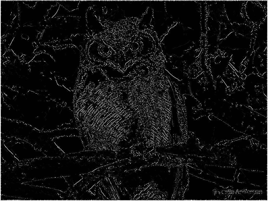
Step 5: Double Threshold
The Double threshold step is simple and straightforward. We set a low threshold and a high threshold. Every gradient magnitude value below the low threshold gets set to 0. Every gradient magnitude value between the low and high threshold gets set to the same low value and we consider them “weak” edges. Finally, every gradient magnitude value above the high threshold gets set to the same high value (usually 255) and we consider them “strong” edges.
fn double_threshold(src: &[u8]) -> Vec<u8> {
    let mut dst = vec![0; src.len()];

    let max = *src.iter().max().unwrap();
    let high = max as f32 * 0.9 / 10.0;
    let low = max as f32 * 0.5 / 10.0;

    (0..src.len()).for_each(|px| {
        let src_px = src[px] as f32;
        if src_px < low {
            dst[px] = 0;
        } else if src_px > high {
            dst[px] = 255;
        } else {
            dst[px] = 25;
        }
    });

    dst
}
It is important to make the threshold values relative to the maximum obtained gradient magnitude value.
Why do we need this step? This is because the previous step (Non-max suppression) is easily susceptible to image noise. From this step we can be sure that every “strong” edge is a true edge, and we will utilize this fact and our “weak” edges in the next step.
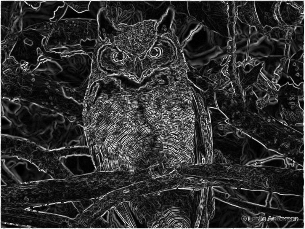
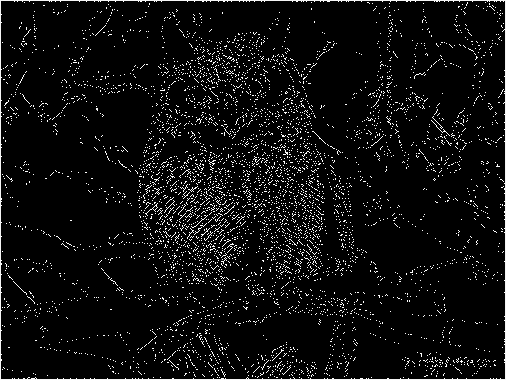
Step 6: Hysteresis
The sixth and final step in the Canny edge detection algorithm. We use the results from the previous step to ensure that only true edges remain in the final image.
We check the neighboring pixels of each “weak” edge pixel, and if any of them are “strong” edge pixels, then we turn the “weak” edge pixel into a “strong” edge pixel (because we can be sure it was not produced from noise). We do this “in-place” because we want previously weak pixels that are now “strong” to also make their neighboring pixels strong.
fn hysteresis(mut src: Vec<u8>, image_width: i32) -> Vec<u8> {
    (0..src.len()).for_each(|px| {
        if src[px] != 255 && src[px] != 0 {
            let blob = [
                // top
                px as i32 - image_width - 1,
                px as i32 - image_width,
                px as i32 - image_width + 1,
                // left and right
                px as i32 - 1,
                px as i32 + 1,
                // bottom
                px as i32 + image_width - 1,
                px as i32 + image_width,
                px as i32 + image_width + 1,
            ];

            for neighbor_px in blob {
                if neighbor_px < 0 || neighbor_px >= src.len() as i32 {
                    continue;
                }
                match src[neighbor_px as usize] {
                    255 => {
                        src[px] = 255;
                        break;
                    }
                    _ => {
                        src[px] = 0;
                    }
                }
            }
        }
    });

    src
}
Conclusion
All-in-all, this was a very fun exercise. I learnt a lot about computer vision, image processing and just math in general from research on specific technical terms used.
It was super fun and cool to see how the image changed in each step, and how changing some values (or making some mistakes in the implementation) affected the resulting image.
If you would like to see the full code (including the method of image loading and drawing the results), check out the repo on my github.
Thanks for reading and stay coding.